Tuesday, July 5, 2011
It's been quiet
Lots of other things going on, but this project isn't buried. Plans are clear and the physics going up! The machine isn't gonna move fast without the engine, and that is YOU !
Friday, November 19, 2010
smaller we go..
New model is soon ready. But new shoes and new crank spindle is needed(WTF?!) When space is at it's minimum, nothing more than enough is acepted. Cycling shoes are ment to use for pedaling, not for walking or looking pretty in your feet. I'v allways been into minimalistic products in racing equipment and this is no exeption. Problem is that ther's no products available that follow this rule of mine (if we ignore Bont TT aero prototype). Custom made? exactly!
The actual model is now more aero but smaller inside. When you try to squeeze the model smaller, more demanding the inner use becomes, that's why shoes need to be reworked, and BB spindle. It looks allready too small to fit inside, hopefully it's not ;)
After few verifications, model is soon ready to be carved out from styrofoam.
Tuesday, November 9, 2010
New direction
Today I made a decision, model needs total updating, it must be more narrow up front, lower at middle and back. That means it will be longer and 300cm limit is a challenge, but I think I can make it. The result should be more efficient vehicle what it was previously. That ofcourse means that the current model will be ripped down completely, but I think this change is necessary. I will also trash my current BB and replace it with a narrow one.
Crank arms have a huge impact to the model, and because I dont see any good reason to go with really short arms due to my inseam lenght of 95cm, I will make it at least more narrow, that will have some impact on the nose area in both dimensions, height and widht by curving the shape differently. Trying to find a compromise between knee movement area, crank width and crank arm lenght. But because time is limiting variable, I will stick with the standard arms for now.
Crank arms have a huge impact to the model, and because I dont see any good reason to go with really short arms due to my inseam lenght of 95cm, I will make it at least more narrow, that will have some impact on the nose area in both dimensions, height and widht by curving the shape differently. Trying to find a compromise between knee movement area, crank width and crank arm lenght. But because time is limiting variable, I will stick with the standard arms for now.
Monday, October 25, 2010
Round nose vs pointy nose
Finally I have a chance to do the tests that has allways bothered me. Round or pointy, hmm thats the question, not an easy answer though.
Both objects are identical exept nose area. Meaning of this is just to see how air acts around those two shapes. Enviromental settings are for both models: 20m/s air speed, surface roughness of 10um.
Force that moving air produces is shown in Newtons. Since air and its behaviour is scalable, object size is not relevant. Only magnitude of differencies rule in this study.
First, air is directional to objects Z-axis which is air direction. In this picture you are able to see pressure map of the objects. On round nose simulation high pressure area shows up in front, higher air drag is present. Sharp nose model has very moderate pressure area causing less drag. By numbers: sharp 0.5N, round 1.3N, so more than twice of force.

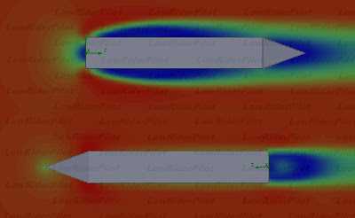
Next test is highly interesting. Side wind of 3m/s is present in axis Y and at the same time 20m/s air is moving in Z axis (direction of movement).
What happens now is that Z-axis directional force remains at level of 0.65N on sharp nose, and 1.6N on round nose. But when looking at the Y axis force, round nose gives a results of 0.44N and sharp gives 0.51N. Colors represent air velocity, scale is between 10 - 25 m/s.

So this tells us what was obvious, round shapes do help on sidewinds, but they cause lot of drag up front. Choosing right shapes could help to maximize efficiency in certain circumstances. This would mean that you should have shape to match every wind conditions, otherways you need to choose which parameters are most important for you, fast movement and less stability in windy conditions or, less fast but better stability. That allways leads into compromise. Whether you choose to run only 200 meters straight line in a calm weather, I'd go with the sharp one. When ride is longer say 6 hours and stability is required to match the enviromental changes, I'd go with something more round shape. Fact is that you can't have both in one packet.
Both objects are identical exept nose area. Meaning of this is just to see how air acts around those two shapes. Enviromental settings are for both models: 20m/s air speed, surface roughness of 10um.
Force that moving air produces is shown in Newtons. Since air and its behaviour is scalable, object size is not relevant. Only magnitude of differencies rule in this study.
First, air is directional to objects Z-axis which is air direction. In this picture you are able to see pressure map of the objects. On round nose simulation high pressure area shows up in front, higher air drag is present. Sharp nose model has very moderate pressure area causing less drag. By numbers: sharp 0.5N, round 1.3N, so more than twice of force.

Next test is highly interesting. Side wind of 3m/s is present in axis Y and at the same time 20m/s air is moving in Z axis (direction of movement).
What happens now is that Z-axis directional force remains at level of 0.65N on sharp nose, and 1.6N on round nose. But when looking at the Y axis force, round nose gives a results of 0.44N and sharp gives 0.51N. Colors represent air velocity, scale is between 10 - 25 m/s.

So this tells us what was obvious, round shapes do help on sidewinds, but they cause lot of drag up front. Choosing right shapes could help to maximize efficiency in certain circumstances. This would mean that you should have shape to match every wind conditions, otherways you need to choose which parameters are most important for you, fast movement and less stability in windy conditions or, less fast but better stability. That allways leads into compromise. Whether you choose to run only 200 meters straight line in a calm weather, I'd go with the sharp one. When ride is longer say 6 hours and stability is required to match the enviromental changes, I'd go with something more round shape. Fact is that you can't have both in one packet.
Sunday, October 24, 2010
Trike transformation
Next study is to test what would it mean to transform this object into three wheel concept. Model is transformed into trike with 2 front wheels and study calculates the drag change. Ther's two pictures, first shows the pressure map and the second shows the velocity map. Velocity plot is a planar cut from a certain distance above the ground where the turbulence caused by the front wheel is highly visible.


And the results, overall force of drag is in Newtons
single wheel(two wheel version) 1.3N
dual front wheel trike 3.5N
Differencies are significant, and probably this is not the best trike designs to think of.
Separating front wheels 40% more away from the body only increased the overall drag to 3.7N. But moving wheels closer to the nose decreased the drag dramatically. Final overall drag is now only 2.5N with object that looks like this.

Saturday, October 23, 2010
Air drag testing with a nose
Since aerodynamics is an area where we dont bump into too often in our everyday life, it must be visualized by testing. Nose down, wide body, body height from the ground etc. all that has a meaning, so best thing is to test their influence and cut off the wings from guessing.
Here I made a study of nose behaviour in air drag. Model is very simple streamline object with ability to easy transformation of it's shape, specially it's height. You can see the model in here.

I tried to simulate what is the effect of the nose height in this model. Since my previous testing with some other models, small changes did not have effect too much to dramatically change the overall drag. Altering the nose height had very little effect to the rest of the model. So It is obvious that the nose itself did do most of the results and it's variations. Tests were made with full 3D part, with full 3D simulations, and artificial ground plane was present. Results here can be seen only in 2D for clarity.
Lets start with the lowest possible height. Without changing the lenght but changing the nose height, we can see steep attack angle in the nose area, specially in the upper part of the nose. More angle you have, more it looks like a flat area to the air causing air pressure to increase. Low nose caused very little of pressure under the body, but increased the nose pressure, so things are not in balance. We could keep the nose down and make that slope less steep by lenghtening the nose, or lowering the object, but since room is required for legs to pedal, that is impossible, and lenghtening would increase the surface area, and we dont want to do that either.

So we make the nose little higher. In this model the slope is divided into half, upper and lower portion are nearly in equal angle and the air cuts into half. Pressure area is the smallest and so is the drag. pressure under the body is moderate, and things looks like more balanced. Slightly more optimized shape in this part could give little more better results.

Third model is with high nose, the slope has moved to the bottom and forces air beneath the model. Increased pressure area and increased drag is present.

Now to the results, speed of the object is 20m/s. Lowest drag was present with the 2nd model, highest drag was with the 1st model, and after a certain point while lifting the nose, drag started to increase again. So with this model, the best place was when top and the bottom slopes were equal and drag increased when slopes were unequal.
Results with numbers, smaller number represents lower drag force in Newtons.
model drag nose height
-----------------------------------
1st 0,94299593 low
2nd 0,772091841 medium
3rd 0,838201198 high
Same object was used in the next study. Does a wheel in front change the previous results? This study shows that it did not. Results are in same direction as in previous one but naturally slightly bigger drag numbers.
Results with numbers, smaller number represents lower drag force in Newtons.
model drag nose height
-----------------------------------
1st 1,281011473 low
2nd 0,989317474 medium
3rd 1,033435136 high

Saturday, October 16, 2010
Brick myth
I'v heard claims about aerodynamics of a brick stone, yep, brick stone has it's own aerodynamics ofcourse. Not sure who really needs this information unless you try to invent some new sport out of it.. But anyway, when there are urban legends, I put my Mythbusters hat on my head and try solve and prove it to be wrong, that's what Mythbuster-guys are doing, so lets play Adam and Jamie for a while ;D. The claim says, that brick with only tail fairing has less drag than the brick with only front fairing.
My goal is not to do tests and get actual accurate results of a brick stone and publish that on a science magazine, that is unnecessary, not even making a wind tunnel out of soda pills and some fancy strain gauges to measure forces what Jamie and Adam would do.
I try to just show the magnitude of the differencies, with simulation tools, someone else can do more precise tests if wants so.
Here's my brick with a sharp nose/tale, air speed is the same at both cases, only air direction is changed 180 deg. Simulations were run with 3D part, here only showing 2D picture as a reference.
Results are nearly what they were in the case of my previous hemisphere test. Flat face towards the wind gave over two times more drag than the sharp face towards the wind, with numbers 1,6N vs. 0,7N.
I'd say that the myth of "flat face towards has less drag", is busted :D

Subscribe to:
Posts (Atom)
