Tuesday, July 5, 2011
It's been quiet
Lots of other things going on, but this project isn't buried. Plans are clear and the physics going up! The machine isn't gonna move fast without the engine, and that is YOU !

Friday, November 19, 2010
smaller we go..
New model is soon ready. But new shoes and new crank spindle is needed(WTF?!) When space is at it's minimum, nothing more than enough is acepted. Cycling shoes are ment to use for pedaling, not for walking or looking pretty in your feet. I'v allways been into minimalistic products in racing equipment and this is no exeption. Problem is that ther's no products available that follow this rule of mine (if we ignore Bont TT aero prototype). Custom made? exactly!
The actual model is now more aero but smaller inside. When you try to squeeze the model smaller, more demanding the inner use becomes, that's why shoes need to be reworked, and BB spindle. It looks allready too small to fit inside, hopefully it's not ;)
After few verifications, model is soon ready to be carved out from styrofoam.
The actual model is now more aero but smaller inside. When you try to squeeze the model smaller, more demanding the inner use becomes, that's why shoes need to be reworked, and BB spindle. It looks allready too small to fit inside, hopefully it's not ;)
After few verifications, model is soon ready to be carved out from styrofoam.
Tuesday, November 9, 2010
New direction
Today I made a decision, model needs total updating, it must be more narrow up front, lower at middle and back. That means it will be longer and 300cm limit is a challenge, but I think I can make it. The result should be more efficient vehicle what it was previously. That ofcourse means that the current model will be ripped down completely, but I think this change is necessary. I will also trash my current BB and replace it with a narrow one.
Crank arms have a huge impact to the model, and because I dont see any good reason to go with really short arms due to my inseam lenght of 95cm, I will make it at least more narrow, that will have some impact on the nose area in both dimensions, height and widht by curving the shape differently. Trying to find a compromise between knee movement area, crank width and crank arm lenght. But because time is limiting variable, I will stick with the standard arms for now.
Crank arms have a huge impact to the model, and because I dont see any good reason to go with really short arms due to my inseam lenght of 95cm, I will make it at least more narrow, that will have some impact on the nose area in both dimensions, height and widht by curving the shape differently. Trying to find a compromise between knee movement area, crank width and crank arm lenght. But because time is limiting variable, I will stick with the standard arms for now.
Monday, October 25, 2010
Round nose vs pointy nose
Finally I have a chance to do the tests that has allways bothered me. Round or pointy, hmm thats the question, not an easy answer though.
Both objects are identical exept nose area. Meaning of this is just to see how air acts around those two shapes. Enviromental settings are for both models: 20m/s air speed, surface roughness of 10um.
Force that moving air produces is shown in Newtons. Since air and its behaviour is scalable, object size is not relevant. Only magnitude of differencies rule in this study.
First, air is directional to objects Z-axis which is air direction. In this picture you are able to see pressure map of the objects. On round nose simulation high pressure area shows up in front, higher air drag is present. Sharp nose model has very moderate pressure area causing less drag. By numbers: sharp 0.5N, round 1.3N, so more than twice of force.

Next test is highly interesting. Side wind of 3m/s is present in axis Y and at the same time 20m/s air is moving in Z axis (direction of movement).
What happens now is that Z-axis directional force remains at level of 0.65N on sharp nose, and 1.6N on round nose. But when looking at the Y axis force, round nose gives a results of 0.44N and sharp gives 0.51N. Colors represent air velocity, scale is between 10 - 25 m/s.

So this tells us what was obvious, round shapes do help on sidewinds, but they cause lot of drag up front. Choosing right shapes could help to maximize efficiency in certain circumstances. This would mean that you should have shape to match every wind conditions, otherways you need to choose which parameters are most important for you, fast movement and less stability in windy conditions or, less fast but better stability. That allways leads into compromise. Whether you choose to run only 200 meters straight line in a calm weather, I'd go with the sharp one. When ride is longer say 6 hours and stability is required to match the enviromental changes, I'd go with something more round shape. Fact is that you can't have both in one packet.
Both objects are identical exept nose area. Meaning of this is just to see how air acts around those two shapes. Enviromental settings are for both models: 20m/s air speed, surface roughness of 10um.
Force that moving air produces is shown in Newtons. Since air and its behaviour is scalable, object size is not relevant. Only magnitude of differencies rule in this study.
First, air is directional to objects Z-axis which is air direction. In this picture you are able to see pressure map of the objects. On round nose simulation high pressure area shows up in front, higher air drag is present. Sharp nose model has very moderate pressure area causing less drag. By numbers: sharp 0.5N, round 1.3N, so more than twice of force.

Next test is highly interesting. Side wind of 3m/s is present in axis Y and at the same time 20m/s air is moving in Z axis (direction of movement).
What happens now is that Z-axis directional force remains at level of 0.65N on sharp nose, and 1.6N on round nose. But when looking at the Y axis force, round nose gives a results of 0.44N and sharp gives 0.51N. Colors represent air velocity, scale is between 10 - 25 m/s.

So this tells us what was obvious, round shapes do help on sidewinds, but they cause lot of drag up front. Choosing right shapes could help to maximize efficiency in certain circumstances. This would mean that you should have shape to match every wind conditions, otherways you need to choose which parameters are most important for you, fast movement and less stability in windy conditions or, less fast but better stability. That allways leads into compromise. Whether you choose to run only 200 meters straight line in a calm weather, I'd go with the sharp one. When ride is longer say 6 hours and stability is required to match the enviromental changes, I'd go with something more round shape. Fact is that you can't have both in one packet.
Sunday, October 24, 2010
Trike transformation
Next study is to test what would it mean to transform this object into three wheel concept. Model is transformed into trike with 2 front wheels and study calculates the drag change. Ther's two pictures, first shows the pressure map and the second shows the velocity map. Velocity plot is a planar cut from a certain distance above the ground where the turbulence caused by the front wheel is highly visible.


And the results, overall force of drag is in Newtons
single wheel(two wheel version) 1.3N
dual front wheel trike 3.5N
Differencies are significant, and probably this is not the best trike designs to think of.
Separating front wheels 40% more away from the body only increased the overall drag to 3.7N. But moving wheels closer to the nose decreased the drag dramatically. Final overall drag is now only 2.5N with object that looks like this.


And the results, overall force of drag is in Newtons
single wheel(two wheel version) 1.3N
dual front wheel trike 3.5N
Differencies are significant, and probably this is not the best trike designs to think of.
Separating front wheels 40% more away from the body only increased the overall drag to 3.7N. But moving wheels closer to the nose decreased the drag dramatically. Final overall drag is now only 2.5N with object that looks like this.

Saturday, October 23, 2010
Air drag testing with a nose
Since aerodynamics is an area where we dont bump into too often in our everyday life, it must be visualized by testing. Nose down, wide body, body height from the ground etc. all that has a meaning, so best thing is to test their influence and cut off the wings from guessing.
Here I made a study of nose behaviour in air drag. Model is very simple streamline object with ability to easy transformation of it's shape, specially it's height. You can see the model in here.

I tried to simulate what is the effect of the nose height in this model. Since my previous testing with some other models, small changes did not have effect too much to dramatically change the overall drag. Altering the nose height had very little effect to the rest of the model. So It is obvious that the nose itself did do most of the results and it's variations. Tests were made with full 3D part, with full 3D simulations, and artificial ground plane was present. Results here can be seen only in 2D for clarity.
Lets start with the lowest possible height. Without changing the lenght but changing the nose height, we can see steep attack angle in the nose area, specially in the upper part of the nose. More angle you have, more it looks like a flat area to the air causing air pressure to increase. Low nose caused very little of pressure under the body, but increased the nose pressure, so things are not in balance. We could keep the nose down and make that slope less steep by lenghtening the nose, or lowering the object, but since room is required for legs to pedal, that is impossible, and lenghtening would increase the surface area, and we dont want to do that either.

So we make the nose little higher. In this model the slope is divided into half, upper and lower portion are nearly in equal angle and the air cuts into half. Pressure area is the smallest and so is the drag. pressure under the body is moderate, and things looks like more balanced. Slightly more optimized shape in this part could give little more better results.

Third model is with high nose, the slope has moved to the bottom and forces air beneath the model. Increased pressure area and increased drag is present.

Now to the results, speed of the object is 20m/s. Lowest drag was present with the 2nd model, highest drag was with the 1st model, and after a certain point while lifting the nose, drag started to increase again. So with this model, the best place was when top and the bottom slopes were equal and drag increased when slopes were unequal.
Results with numbers, smaller number represents lower drag force in Newtons.
model drag nose height
-----------------------------------
1st 0,94299593 low
2nd 0,772091841 medium
3rd 0,838201198 high
Same object was used in the next study. Does a wheel in front change the previous results? This study shows that it did not. Results are in same direction as in previous one but naturally slightly bigger drag numbers.
Results with numbers, smaller number represents lower drag force in Newtons.
model drag nose height
-----------------------------------
1st 1,281011473 low
2nd 0,989317474 medium
3rd 1,033435136 high

Here I made a study of nose behaviour in air drag. Model is very simple streamline object with ability to easy transformation of it's shape, specially it's height. You can see the model in here.

I tried to simulate what is the effect of the nose height in this model. Since my previous testing with some other models, small changes did not have effect too much to dramatically change the overall drag. Altering the nose height had very little effect to the rest of the model. So It is obvious that the nose itself did do most of the results and it's variations. Tests were made with full 3D part, with full 3D simulations, and artificial ground plane was present. Results here can be seen only in 2D for clarity.
Lets start with the lowest possible height. Without changing the lenght but changing the nose height, we can see steep attack angle in the nose area, specially in the upper part of the nose. More angle you have, more it looks like a flat area to the air causing air pressure to increase. Low nose caused very little of pressure under the body, but increased the nose pressure, so things are not in balance. We could keep the nose down and make that slope less steep by lenghtening the nose, or lowering the object, but since room is required for legs to pedal, that is impossible, and lenghtening would increase the surface area, and we dont want to do that either.

So we make the nose little higher. In this model the slope is divided into half, upper and lower portion are nearly in equal angle and the air cuts into half. Pressure area is the smallest and so is the drag. pressure under the body is moderate, and things looks like more balanced. Slightly more optimized shape in this part could give little more better results.

Third model is with high nose, the slope has moved to the bottom and forces air beneath the model. Increased pressure area and increased drag is present.

Now to the results, speed of the object is 20m/s. Lowest drag was present with the 2nd model, highest drag was with the 1st model, and after a certain point while lifting the nose, drag started to increase again. So with this model, the best place was when top and the bottom slopes were equal and drag increased when slopes were unequal.
Results with numbers, smaller number represents lower drag force in Newtons.
model drag nose height
-----------------------------------
1st 0,94299593 low
2nd 0,772091841 medium
3rd 0,838201198 high
Same object was used in the next study. Does a wheel in front change the previous results? This study shows that it did not. Results are in same direction as in previous one but naturally slightly bigger drag numbers.
Results with numbers, smaller number represents lower drag force in Newtons.
model drag nose height
-----------------------------------
1st 1,281011473 low
2nd 0,989317474 medium
3rd 1,033435136 high

Saturday, October 16, 2010
Brick myth
I'v heard claims about aerodynamics of a brick stone, yep, brick stone has it's own aerodynamics ofcourse. Not sure who really needs this information unless you try to invent some new sport out of it.. But anyway, when there are urban legends, I put my Mythbusters hat on my head and try solve and prove it to be wrong, that's what Mythbuster-guys are doing, so lets play Adam and Jamie for a while ;D. The claim says, that brick with only tail fairing has less drag than the brick with only front fairing.
My goal is not to do tests and get actual accurate results of a brick stone and publish that on a science magazine, that is unnecessary, not even making a wind tunnel out of soda pills and some fancy strain gauges to measure forces what Jamie and Adam would do.
I try to just show the magnitude of the differencies, with simulation tools, someone else can do more precise tests if wants so.
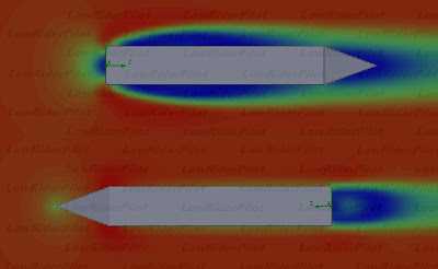
Here's my brick with a sharp nose/tale, air speed is the same at both cases, only air direction is changed 180 deg. Simulations were run with 3D part, here only showing 2D picture as a reference.
Results are nearly what they were in the case of my previous hemisphere test. Flat face towards the wind gave over two times more drag than the sharp face towards the wind, with numbers 1,6N vs. 0,7N.
I'd say that the myth of "flat face towards has less drag", is busted :D
My goal is not to do tests and get actual accurate results of a brick stone and publish that on a science magazine, that is unnecessary, not even making a wind tunnel out of soda pills and some fancy strain gauges to measure forces what Jamie and Adam would do.
I try to just show the magnitude of the differencies, with simulation tools, someone else can do more precise tests if wants so.
Here's my brick with a sharp nose/tale, air speed is the same at both cases, only air direction is changed 180 deg. Simulations were run with 3D part, here only showing 2D picture as a reference.
Results are nearly what they were in the case of my previous hemisphere test. Flat face towards the wind gave over two times more drag than the sharp face towards the wind, with numbers 1,6N vs. 0,7N.
I'd say that the myth of "flat face towards has less drag", is busted :D

Wednesday, October 13, 2010
Hemisphere test >:-)
Since low aerodynamic drag is a base of movement in these vehicles, I will post my short study of 15 minutes. This study clearly shows the difference between flat surface vs round surface and reaction in air flow around them. Because the study is not done in scientific manners, I created basic shapes without any details or minor flluctuations on their surfaces, these results are not exactly true offcourse, just giving some quidance of this phenomenon.
The study contains a solid 50cm hemisphere, airflow is 10meters/s and surface is theoretically perfect with roughness of 0. Both hemispheres are equal, only variation is their air flow direction, the other is flat face to wind and the other is round face to wind. The results are: flat face to wind gave 13N of force and round face to wind gave 6N of force, so more than twice of force is generated when flat face is put towards the wind.

Previously made simulation with streamlined body (see previous posts) gave results 7N @ 20m/s, which is nearly the same as 50cm hemisphere but with double speed ! With equation F = ½ s v² A Cv , force of drag will give Cv value of 0.095 with given parameters. But frontal area needs to be rechecked in the process when, for example, the bubble is added. So there is a lot of variables and Cv value is not even close to it's practical and real value.
The study contains a solid 50cm hemisphere, airflow is 10meters/s and surface is theoretically perfect with roughness of 0. Both hemispheres are equal, only variation is their air flow direction, the other is flat face to wind and the other is round face to wind. The results are: flat face to wind gave 13N of force and round face to wind gave 6N of force, so more than twice of force is generated when flat face is put towards the wind.

Previously made simulation with streamlined body (see previous posts) gave results 7N @ 20m/s, which is nearly the same as 50cm hemisphere but with double speed ! With equation F = ½ s v² A Cv , force of drag will give Cv value of 0.095 with given parameters. But frontal area needs to be rechecked in the process when, for example, the bubble is added. So there is a lot of variables and Cv value is not even close to it's practical and real value.
Thursday, October 7, 2010
Mock Up
I totally forgot to show the mockup concept I worked during the summer. It is basically a 2x4 block of wood as a base with seat, BB-support and cranks attached to it. It's not a high tech unit, but it does basic things you need, all can be adjusted and get the quidelines of what can be expected on real thing. This mock up was later totally updated with bigger seat and frame curves along it's shape with accurate measurements which were transported to 3D-program. Previous 3d-model which was made with only few simple not accurate, quideline type of measurements, was totally foolish, and had a bit of a problem to solve it, I even felt "damn,this is going to be sh*t". But as so many times before, I had to think it fresly from the start, with the basics again, and I changed my sitting position closer to the ground and a bit more backwards and few other things and remeasured everything and squeeged all air out of it and shape became nice tube-like form and the overall shape was possible to make very streamlined, and I even got it more narrow and lower. And the most important thing is that I fit inside, into shape that looks impossible and ridicilously small, even unreal, but it's there.
It's funny to realize that only few measurements master the whole design, and there is not much you can do about it, form just pops out from you and your own body dimensions.
I concider myself lucky, and unlucky. For many sports size is not a benefical if it's on the bigger side, that is my problem, I'm on the wrong side. But to be big, at least you can do is to be narrow, and that's what I am. If one is big with wide shoulders and muscular upper body, I wonder what would the vehicle be like, wide for sure, and that is not optimum.

It's funny to realize that only few measurements master the whole design, and there is not much you can do about it, form just pops out from you and your own body dimensions.
I concider myself lucky, and unlucky. For many sports size is not a benefical if it's on the bigger side, that is my problem, I'm on the wrong side. But to be big, at least you can do is to be narrow, and that's what I am. If one is big with wide shoulders and muscular upper body, I wonder what would the vehicle be like, wide for sure, and that is not optimum.

Sunday, October 3, 2010
Computational Fluid Dynamics
Playing with my new toy, CFD-simulation tool. Just figuring out what are the things I should and can do, and what I should not even concider.
Because aerodynamics is a whole new world, and you could spend your whole life with searching the right shape, I just kept it simple and created the basic quidelines which to follow. Here is one of the samples I have tested. Forward directional force is aprx. 7 Newtons @ 20m/s, this model is without a bubble.

Because aerodynamics is a whole new world, and you could spend your whole life with searching the right shape, I just kept it simple and created the basic quidelines which to follow. Here is one of the samples I have tested. Forward directional force is aprx. 7 Newtons @ 20m/s, this model is without a bubble.

Tuesday, September 21, 2010
Wow, my weeks took longer than I expected ;-)
Hi, haven't been here for a while, strange, but that's how it goes. Project, that streamlined bike has not been buried, it's still going, going stronger and with determination, which has never been lost. The whole spring and summer went with training and traveling, skating hasn't been my main goal anymore, it's biking, and only biking. During spring and summer I'v done biking about 12 to 15 hours a week, and that pace should be kept up during wintertime. Only race I took part this year was TdH-2010, which I passed with 4:07, that included one crash and two technical problems, so I'm pretty satisfied for my result, and I'v done racebiking only twice this summer, mainly focusing on mountainbiking, so from that perspective I'm more than happy. MTB is well deserved change to sometimes boring straight paved roads.
Now, rainy weather is here to stay and forces me to stick inside and finally I have some time to put into this project. During summer I do have done something, more modeling, few more new softwares and CFD simultors and virtual wind tunnels have been tested, and some new parts designed including new set of wheels and rear suspension concept and put also some effort into "landing gear" which seems to be quite challenging task, not to mention some new electronics focused only for competition purposes, so lots of stuff in my head waiting to come out some day.
Now, more modeling, final shape is just there, on fingertips :D

Now, rainy weather is here to stay and forces me to stick inside and finally I have some time to put into this project. During summer I do have done something, more modeling, few more new softwares and CFD simultors and virtual wind tunnels have been tested, and some new parts designed including new set of wheels and rear suspension concept and put also some effort into "landing gear" which seems to be quite challenging task, not to mention some new electronics focused only for competition purposes, so lots of stuff in my head waiting to come out some day.
Now, more modeling, final shape is just there, on fingertips :D

Sunday, November 22, 2009
Next week and weekend
Next week I should have a packet with some of the items i need to be able to build a mockup of a streamliners basic lines. It would tell a huge amount of information about the whole project, it's measures, my pedaling position and I really get the first feeling of the vehicle. Up to now, everything has been pretty much just an image of the concept, but soon that all will be put into some form. So the next few weeks are really, really interesting.
Until then I'v put my effort into training, this weekend was exceptionally hard. We had a coach from Denmark to put our physical abilities under a test. 16 hours of training, theory, all technical stuff and finally a brutal strenght torture..
Until then I'v put my effort into training, this weekend was exceptionally hard. We had a coach from Denmark to put our physical abilities under a test. 16 hours of training, theory, all technical stuff and finally a brutal strenght torture..
Friday, November 20, 2009
Low steering..
Front suspension, well I'v seen them a lot, but not like this. This is a idea that came from center pivot suspension. But instead of using center pivot hub I made one idea of using regular hub and using linear arms to replace the regular fork. This setup would be more sturdy, but because of many joints and bearings, definately will be more heavy, but what ever we wish to accomplish, ther's an idea behind it.
Few words about the design, hub is joined into arms by 4 bearings, and the arms are joined into control arms by aother set of bearings, control arm is joined into frame by bearings. The result is that when the arms are moved back, the other one moves forward, hub turns into desired direction and there we have a steering. I could say this is a low side steering or arm-steering.
Offcourse when upside fork is removed, we loose the upper frame where we can attach the transmission, but instead of putting it into above the wheel, in this idea the transmission is below the wheel, actually on side of the wheel.
Actually Im not sure is this any where good way to build a steering, but one advantage is that it is slim, very low in construction, but probably the heavy side because of the bearings and arms, at least its more heavy than regular upright fork.
Model is very simple, just to test the idea and see what is there to go wrong, and without testing, hard to say anything more about it.

Few words about the design, hub is joined into arms by 4 bearings, and the arms are joined into control arms by aother set of bearings, control arm is joined into frame by bearings. The result is that when the arms are moved back, the other one moves forward, hub turns into desired direction and there we have a steering. I could say this is a low side steering or arm-steering.
Offcourse when upside fork is removed, we loose the upper frame where we can attach the transmission, but instead of putting it into above the wheel, in this idea the transmission is below the wheel, actually on side of the wheel.
Actually Im not sure is this any where good way to build a steering, but one advantage is that it is slim, very low in construction, but probably the heavy side because of the bearings and arms, at least its more heavy than regular upright fork.
Model is very simple, just to test the idea and see what is there to go wrong, and without testing, hard to say anything more about it.

Wednesday, November 4, 2009
Adjustable cranks
Carbon cranks with adjustment from 150mm up to 180mm. Q factor is 135mm, but easily adjusted by lenght of the spindle. BB is with no threads, and oversized for strenght. Spindle is hollow titanium tube. Spider is integrated. Chainring is with 130mm spacing. Weigh is 1000g including spindle, cranks and chainring, but it's still a solid object so weigh should come down when putting this together in real.
Why?, The reason is obvious, components with decent qualities aren't available, qualities such as lenght, weight, Q-factor, BB's etc. are not packed in one killer-product package, you should have 3-4 cranks, and combine those into one. Thats what is done in here. Adjustable lenght, sturdy BB, simple design, custom narrow, aero.
The cause is the world of standards where bikeworld stands, this is my little tiny snap into it's anxiousness to keep oldish axioms no matter how bad they are in modern standards point of view. Good example is the BB. The thread size and the shell radius is from the age when Adam met Eve. The shell and it's components were good for the use at that time, but today where DH, sick jumps and rude bashing is the use where bikes and it's components are put, shell is ridicilously underbuilt as is the bearings. Even that ISIS is great as a crank attachement, it lacks in BB, bearing balls are smaller than a head of the needle..
ISIS-Overdrive would be a perfect combination of strenght and easyness, sealed concept in a modern size.. but it lacks the support from the market, there are no bikes out there to use the standard, thatway ISIS-OD BB's are not widely available, if not at all. Dynamic bike world, where the wheel is allmost reinvented every year, some things never change.

I ran an FEA analysis to this part, material was 6061 aluminium.

Why?, The reason is obvious, components with decent qualities aren't available, qualities such as lenght, weight, Q-factor, BB's etc. are not packed in one killer-product package, you should have 3-4 cranks, and combine those into one. Thats what is done in here. Adjustable lenght, sturdy BB, simple design, custom narrow, aero.
The cause is the world of standards where bikeworld stands, this is my little tiny snap into it's anxiousness to keep oldish axioms no matter how bad they are in modern standards point of view. Good example is the BB. The thread size and the shell radius is from the age when Adam met Eve. The shell and it's components were good for the use at that time, but today where DH, sick jumps and rude bashing is the use where bikes and it's components are put, shell is ridicilously underbuilt as is the bearings. Even that ISIS is great as a crank attachement, it lacks in BB, bearing balls are smaller than a head of the needle..
ISIS-Overdrive would be a perfect combination of strenght and easyness, sealed concept in a modern size.. but it lacks the support from the market, there are no bikes out there to use the standard, thatway ISIS-OD BB's are not widely available, if not at all. Dynamic bike world, where the wheel is allmost reinvented every year, some things never change.

I ran an FEA analysis to this part, material was 6061 aluminium.

Sunday, November 1, 2009
Week off
So, to be short this time, being sick all week, really did't have too much effort to put into the project. But I managed to order my first components, also had some conversation about one another project I should go thru, so lots of stuff going on in here. And also made a really unique front wheel drive/steering system which might appear into these pages after i finish the idea in some level.
Next thing is to build a mockup with the components I'm having and also make some more designs.
-LRPilot
Next thing is to build a mockup with the components I'm having and also make some more designs.
-LRPilot
Sunday, October 25, 2009
24" front disc wheel
Since I have long legs (95cm inseam) I'd like to go with bigger front wheel too, front wheel is normally 20", but since my physical size accepts bigger wheels, I'd rather go with better rolling wheels than leave that advantage unused.
Many tests have shown and also practise, that the most aerodynamic wheel is a disc. On upright bike TT races, tens of seconds can be won with discs, and comparing the other things you CAN do to decrease your air resistance, is the helmet, frame, suit, shoes etc, minor things. But since we are not making upright bike here, helmet and suit is irrelevant issue.
No question wheel aerodynamics is important issue, so lets buy an aero disc ...ok..what are we talking about? Let's first see the requirements we have. Let's assume that the regular 8-10 cassette is too wide and you keep banging your leg into it causing driving to be impossible, whats our next step? narrow the hub and make it single speed. How about disc brakes you want to use? no problem.. ok..we might find something to cover our requirements so far, but when we add one thing, 24" size, we have no options left. Even that world seems to be full of bike components and all the variations you might think of, thats hardly so. Bike world stands on standards and compatibility. Also the usage limits the manufacturing, why build something what is not needed? But when we are buiding radical vehicle for radical usage, should we stick with the standard products?, in some items we should, but when there is not what we need? Thats why, lets create unique designs to perfectly suit to our purpose. Here is my few hours of work, and here are the specs so far:
Disc:
Size: 24"
Tyre: tubular 24" x 1"
construction: Carbon on honeycomb
hub:
construction: aluminium, thread-on freewheel, double-flange design, 6 bolt IS mount
bearings: double SKF 6000
freewheel: White Industries ENO, 1.37 x 24 tpi
weight: 260g inc bearings, (exc. axel & freewheel)
width: 60mm (exc. freewheel)
axle: 10mm
Offcourse this would mean that the gearing must be elsewhere, but it's to be seen later..
Also put some colourfull graphics to tease the imagination, text is just what came to my mind at first..

Many tests have shown and also practise, that the most aerodynamic wheel is a disc. On upright bike TT races, tens of seconds can be won with discs, and comparing the other things you CAN do to decrease your air resistance, is the helmet, frame, suit, shoes etc, minor things. But since we are not making upright bike here, helmet and suit is irrelevant issue.
No question wheel aerodynamics is important issue, so lets buy an aero disc ...ok..what are we talking about? Let's first see the requirements we have. Let's assume that the regular 8-10 cassette is too wide and you keep banging your leg into it causing driving to be impossible, whats our next step? narrow the hub and make it single speed. How about disc brakes you want to use? no problem.. ok..we might find something to cover our requirements so far, but when we add one thing, 24" size, we have no options left. Even that world seems to be full of bike components and all the variations you might think of, thats hardly so. Bike world stands on standards and compatibility. Also the usage limits the manufacturing, why build something what is not needed? But when we are buiding radical vehicle for radical usage, should we stick with the standard products?, in some items we should, but when there is not what we need? Thats why, lets create unique designs to perfectly suit to our purpose. Here is my few hours of work, and here are the specs so far:
Disc:
Size: 24"
Tyre: tubular 24" x 1"
construction: Carbon on honeycomb
hub:
construction: aluminium, thread-on freewheel, double-flange design, 6 bolt IS mount
bearings: double SKF 6000
freewheel: White Industries ENO, 1.37 x 24 tpi
weight: 260g inc bearings, (exc. axel & freewheel)
width: 60mm (exc. freewheel)
axle: 10mm
Offcourse this would mean that the gearing must be elsewhere, but it's to be seen later..
Also put some colourfull graphics to tease the imagination, text is just what came to my mind at first..

Wednesday, October 21, 2009
moving into 3D
Exiting moment, shape actually got it's depth in 3D, and you can turn it around and actually see it in real, if you have a good imagination...
Lots of stuff can be seen in this early 3d-model. Pedal box in 3d, wow! I can guarantee that it's tight allright..
Also the overall shape from every direction can be seen. Back section actually was pretty difficult to adjust, shoulder width and very quick shape transformation into very thin tale made the mid-section wider because of the smooth curves I tried to achieve along the lenght, pretty much unexpected situation, but it gave more room for legs to move and the airflow is better now than in my model I made without the aid of 3D. So I think 3D saved a lot in here..
Wireframe-model, not telling much about the design as a picture.. but its there, hiding somewhere inside the messy chaos..

Lots of stuff can be seen in this early 3d-model. Pedal box in 3d, wow! I can guarantee that it's tight allright..
Also the overall shape from every direction can be seen. Back section actually was pretty difficult to adjust, shoulder width and very quick shape transformation into very thin tale made the mid-section wider because of the smooth curves I tried to achieve along the lenght, pretty much unexpected situation, but it gave more room for legs to move and the airflow is better now than in my model I made without the aid of 3D. So I think 3D saved a lot in here..
Wireframe-model, not telling much about the design as a picture.. but its there, hiding somewhere inside the messy chaos..

Sunday, October 18, 2009
"LS"-project, what's that?
Perhaps many of us would think that this all is just putting ready made pieces together and building, but that's just the top of the project. In order to make things happen, you need a plan to stick with, you need to think, sketch, find out, sketch again, and at the same time keep yourself in a shape by doing hourly exercises, well back to where things start.
To be able to make things right at the first without endless iteration rounds, and costly material expences, you need to start from the scratch with no assumptions with no thoughts like, "yeah, I just do something and everything turns good, I think..", WRONG ! Streamliners are like individuals, unique designs made for one person only, the driver. What is good for someone, isn't necessary good for someone else, thats where you need sister-projects. But I found out that before you can start building your sister project I introduced few days back, I need "little sister"-project, which makes sure that sister project will be a success and I don't need to rip it apart because of some stupid mistake I forgot. So that is why I will do this, lets say "LS"-project before "S"-project.
LS-project is a first geometry construction where driver is planted into a machine and its geometry. In LS-project you make your first study of crank setup, seating position, seating angle, crank height, crank distance, your FOV and height and lenght study. When all these are, lets say, in some form, you need to confirm your decisions. Because the streamliner is a faired bike, you need to keep that in mind in every point of the project. No matter if you have the perfect seat and crank setup, you cant be sure if that is rational what comes to fairing. If your cranks stick out from the smooth line of fairing, what do you do? move cranks, or make fairing bigger? what if perfect crank and seat height will block your FOV (field of view)? what do you do, and with what costs?, do you loose your perfect crank position or do you loose your slick shape, which one is less worst? Anyone ever heard the word 'compromise'? xD
To avoid the worst, fairing and its design must be kept in mind all the time. When you have your crank and seat in place in this 'LS'-project, you need to determine the fairing aswell in this very early state. First things first, you need to determine your pedal box by rotating your pedals and making notes of your cranking.
I'v done several sketches and measurements of my feet and my pedal-box, but nothing beats the real world modeling.
Below is my LS-project. Actually it's a jig where everything can be adjusted to find the correct geometry. Once you have your pieces in place, you need to measure your pedal box and all the space you need to have inside the fairing. When having those measurements, you need to transform these measures into 3D world to be able to make a 3d-model sketch out of it, but that is just the half of the "LS"-projects story..

To be able to make things right at the first without endless iteration rounds, and costly material expences, you need to start from the scratch with no assumptions with no thoughts like, "yeah, I just do something and everything turns good, I think..", WRONG ! Streamliners are like individuals, unique designs made for one person only, the driver. What is good for someone, isn't necessary good for someone else, thats where you need sister-projects. But I found out that before you can start building your sister project I introduced few days back, I need "little sister"-project, which makes sure that sister project will be a success and I don't need to rip it apart because of some stupid mistake I forgot. So that is why I will do this, lets say "LS"-project before "S"-project.
LS-project is a first geometry construction where driver is planted into a machine and its geometry. In LS-project you make your first study of crank setup, seating position, seating angle, crank height, crank distance, your FOV and height and lenght study. When all these are, lets say, in some form, you need to confirm your decisions. Because the streamliner is a faired bike, you need to keep that in mind in every point of the project. No matter if you have the perfect seat and crank setup, you cant be sure if that is rational what comes to fairing. If your cranks stick out from the smooth line of fairing, what do you do? move cranks, or make fairing bigger? what if perfect crank and seat height will block your FOV (field of view)? what do you do, and with what costs?, do you loose your perfect crank position or do you loose your slick shape, which one is less worst? Anyone ever heard the word 'compromise'? xD
To avoid the worst, fairing and its design must be kept in mind all the time. When you have your crank and seat in place in this 'LS'-project, you need to determine the fairing aswell in this very early state. First things first, you need to determine your pedal box by rotating your pedals and making notes of your cranking.
I'v done several sketches and measurements of my feet and my pedal-box, but nothing beats the real world modeling.
Below is my LS-project. Actually it's a jig where everything can be adjusted to find the correct geometry. Once you have your pieces in place, you need to measure your pedal box and all the space you need to have inside the fairing. When having those measurements, you need to transform these measures into 3D world to be able to make a 3d-model sketch out of it, but that is just the half of the "LS"-projects story..

Monday, October 12, 2009
Wrap around
Wild sketching for fun. In my last post I introduced my first lowracer concept, I decided to play slightly further by wrapping it with a fairing and here is a result, 'lowliner', lol. It's a little bit different than previous sketch models, it's shorter and lower, and so unready, but I was in a creative mood, it's made to look like a mean mile eater machine :D


Sunday, October 11, 2009
Lowracer concept - first appearance
'Sister-project' I would say, but to be able to make decisions, I need a good platform to test particulary driving position, which is the most critical and also unknown, how else you could ride hours unless you feel comfortable. However, these bikes are not ment to replace your livingroom sofa, but if you make a critical error in your positioning, you may not be able to pedal properly or get a good breathing. Also to driveability and manoeuvrability is very important to test, and does it have some bad habits. The design is different when it's a lowracer and not a streamliner, but at least you can have a hint of the future what's head of us. That is the meaning of the lowracer concept.
There is one thing that might look odd, it's mainly because the construction is different what it would be in a monococue streamliner, but the ground clearance is very low mainly because of the main tubing under the seat. The seating height represents the height what it would be in a monococue construction, you literally 'sit on the bottom', so that is where you need to sit in this lowracer.
Steering is something you can't deside before you have something you can fit yourself in, so that will be a matter of experimenting and it is left out at this point. Three different ways are possible, downbar, upbar or sidebar. Sidebar and 'side-steering' sounds complicated and strange.., but I feel I will give it a try :)
The height of the construction is very important, if you want to make it look like a typical lowracer, it would be much "flatter" , driver laying more in his back than sitting upwards, but streamliner is a vehicle of compromises. More upwards it means shorter lenght, better view, bigger overall height. Laying down means longer bike, low view, perhaps heavier bike. As we know now, pedal-box is the critical and most guiding issue in a liner where everything must fit inside the fairing and still make a good aerodynamics. So if you have a big pedal box like I have (big feet, long cranks), it's pointless to make a long vehicle because it also needs to be quite high. So before you think that more lower the better, maybe, but not in all cases.
Here we have a sketch of the lowracer design.

There is one thing that might look odd, it's mainly because the construction is different what it would be in a monococue streamliner, but the ground clearance is very low mainly because of the main tubing under the seat. The seating height represents the height what it would be in a monococue construction, you literally 'sit on the bottom', so that is where you need to sit in this lowracer.
Steering is something you can't deside before you have something you can fit yourself in, so that will be a matter of experimenting and it is left out at this point. Three different ways are possible, downbar, upbar or sidebar. Sidebar and 'side-steering' sounds complicated and strange.., but I feel I will give it a try :)
The height of the construction is very important, if you want to make it look like a typical lowracer, it would be much "flatter" , driver laying more in his back than sitting upwards, but streamliner is a vehicle of compromises. More upwards it means shorter lenght, better view, bigger overall height. Laying down means longer bike, low view, perhaps heavier bike. As we know now, pedal-box is the critical and most guiding issue in a liner where everything must fit inside the fairing and still make a good aerodynamics. So if you have a big pedal box like I have (big feet, long cranks), it's pointless to make a long vehicle because it also needs to be quite high. So before you think that more lower the better, maybe, but not in all cases.
Here we have a sketch of the lowracer design.

Subscribe to:
Posts (Atom)
